all figures
COPYRIGHT
Inst.f.Chromatography

Web Design
                    Multi Integration

Quantitation in Planar Chromatography, a new Concept: Multi Integration

µ-PLC is circular. The sample spot is circular. In order to have the highest possible separation efficiency available, the circular sample spots are focussed, either one times or twice. The chromatogram starts with sharp bows in  case several samples are to be separated. Or we have only one sample, which separates into full circles. The latter is standard if we use µ-PLC for trace or sub trace analyses.

Therefore the substance bows are much longer than the short lines in line sprayed instrumentalized HPTLC or even only single spots in linear TLC / HPTLC. Long bow lines in µ-PLC allow for multi scanning and multi integration. More than three - in minimum four or up to 16 tracks can be scanned and integrated. Spot based sampling allows only one track to scan with the special danger that the linear track does not keep the substance positions completely in case of non linear gradient effects. Top instrumentalized - latest - HPTLC chromatograms may be free from the just mentioned gradient problem but nevertheless - up to now - one track of substances in line format gets only one signal per substance position. To get repeatability data - the repeatability standard deviation and the analytical uncertainty value - the same tracks can be re integrated. This can be repeated with the same sample positioned at other tracks of the linear HPTLC plate. Two or three - for mass statistics also many more sample tracks - can be scanned and the data integrated. But this is always a special case. It is not the standard procedure in HPTLC quantitation, because the analyst wants to have as many differing samples as possible quickly.

In µ-PLC quantitation it is standard to have per sample position always at least four tracks available for scanning and integration, but - and this is the power of the new concept - but each scan at a changed local position. Many more compared tracks can be scanned and integrated. Each track has its own position. The track position is changed by a selectable angle. The smallest is one degree, the largest change angle is 22 degree from track to track. See figure 24 to 27 and 36 in the µ-plc pictogram chapter. This multi scanning results in comparison, not in repetition. Another fundamental difference between the standard quantitation concept of to day and Multi Integration. So as data quality value we can get the comparability standard deviation.  This sounds like much effort but now we will see the reason: By changing the angle position we do not touch the substance signal size. It is at all angle positions equal (+- statistics values). The key effect is: on each next angel position we have the same substance signal but not the same  plate structure signal.

Here are two formulas for the reduction of the plate structure signal. As mentioned already again - because it is widely unknown or simply a suppressed fact - TLC / HPTLC layer structure is THE source of the worst systematic standard error in all PLC quantitation. It reduces calibration line quality data by a factor of ten. It is treated like electronic noise. This must be classified as mathematical-statistically illegal. Plate structure is simply a primitive but too large constant systematic error. One could measure the structure over the complete plate area, store the data in a computer memory, scan the chromatogram and subtract the structure signal. This however must be done with utmost local precision by +- 0.1 mm accuracy in both area directions X and Y. The correct positioning of both data sets - the structure data set and the raw structure containing chromatogram data set - costs a lot of memory and time. Fast mathematics and processors are necessary in the LAB computer.

Much easier: Multi scan at differing positions (N=4, or higher). Add the raw data sets to a total sum. Divide by the numbers of done scans (by N=4 or higher).  The structure (only the structure) is reduced by the factor of 4 or higher.
This is done by Multi Integration.

rekbild1014

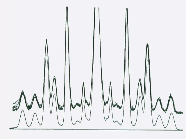
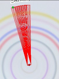
Figure 1: the upper part with the rough chromatogram lines overlapped shows 16 angular changed tracks scanned by a modified CAMAG scanner. The lower part with the single line chromatogram shows the mean of 16 scans divided by 16. Both chromatogram parts - the upper rough one and the “smoothed looking” one have electronic noise in the signal, but it is simply not visible in the graphics because of large enough signals. Plate structure signal and and real electronic noise show easily a relation of 10 to 1. Above you see a “multi scan” as shown in figure 62 - click on MULTISCAN, select figure 62 and click on the found pictogram 62. Click in the figure caption of the enlarged figure 62 onto the blue clickword HERE. This will bring you back to this chapter you are just reading.

To repeat what we did as shown in figure 1 above: Add the signals of all compared integration data and divide the sum by the number of differing tracks. This keeps the size of the
signal. All compare scans are for a given substance at the same radius position of the circular run. However all signal parts caused by the plate structure are NOT at the same position. Structure signals are statistically distributed over the whole chromatogram area. By dividing their sum we reduce the structure signal values. This improves drastically the accuracy of the substance signals. Therefore multi integrated chromatograms show a much better comparable standard deviation, thus a much smaller uncertainty as all classical quantitation based on the regulated linear procedure.

The author knows, that statistics is something chemists do not like so much, but all are top in reading and understanding analog chromatograms. The experiment as shown in figure 1 was already done 30 years ago with software written by M. Prosek, A. Medja, both guests at IfC Bad Duerkheim, and the author when we could control a special version of a CAMAG scanner with our own software.

In µ-PLC we realized an up to now not known perfect constancy of the substance position on the plate when scanning at differing angles. In linear TLC the substance position is expressed as Rf value. For good reasons we leave the Rf-mode for qualitative evaluations. Instead we describe the position of a substance as the ratio of Pi / Pf = Pr. Pi is the length of the substance path measured from on the center. Pf is the length of the mobile phase path from the center to the front. We can calculate linear Rf values from classically measured Rf values in circular PLC, but we prefer the Pr concept due to the focussing technique. The µ-PLC separation starts from the focussing circle position, not from the former sample position. The comparability standard deviation of Pr data is often smaller than +- 0.1 % whilst Rf values in linear TLC never reach such a precision level.

This is a next reason, why µ-PLC quantity values show comparability standard deviation data often better than +- 0.5 % - in best cases down to +- 0.05 %.

NOTE: In all cases these are quality data after the multi integrated raw values have been summed up and divided by the number of used tracks per position. The integration position in a circular chromatogram can be selected freely by the analyst. Of course freedom is something which disappeared in modern analysis by over regulation but qualified analysts can use procedural freedom at its best. They know the way to get best possible and still correct analytical results because they use the full range of the beauty of planar chromatography. But they know that beauty is nothing without brain.

Multi Integration is very flexible. Nearly all effects are software controlled.
In the following we compare the number of multi scans and the width of the tracks.
Narrow tracks handle chromatograms with strong signals. Wide tracks are good for chromatograms containing weak signals. In order to keep results comparable we use the same chromatogram - this is a chromatogram for testing layer quality.


bild.MI-4-1-11

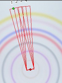
Figure 2 above:

Track number:  4
Track width:     11 units

The analog chromatogram with all 4 tracks and the graphical mean track are overlapped.
 

bild-16-1-11

Figure 3 above:

Track number:    16
Track width:       11 units

The analog chromatogram with all 4 tracks and the graphical mean track are overlapped.
 

bild-MI-4-4-24-base

Figure 4 above:

Track number:  4
Track width:      24 units.

The analog chromatogram with all 4 tracks and the graphical mean track are overlapped.
 

fig6

Figure 5, left side :
these are the analog data from the tracking conditions seen in figure 4 above

These are five overlapped  chromatograms - four tracks scanned and the fifth data set is the structure reduced graphical mean of all four.

Only near to the front (Rp at about 0.95 in figure left) we see differences in the analog chromatogram values.

Figure 5

scroll bar -->

fig6-sp

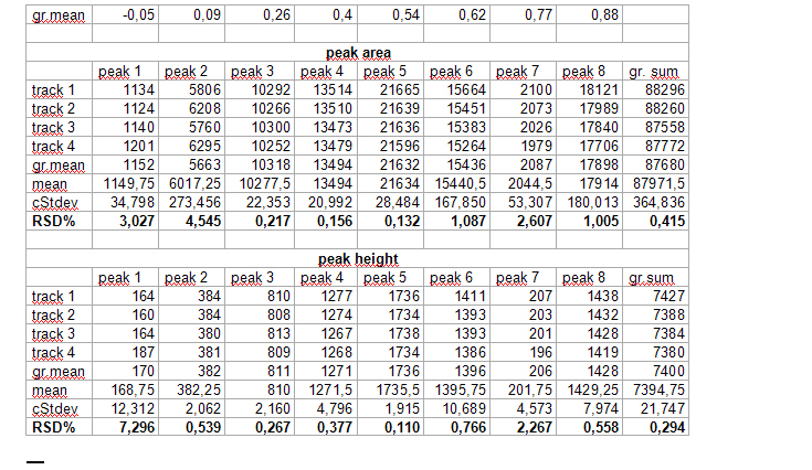
Figure 6: Digital data of the multi integrated area in figure 4 above. For the height and the area data we see comparability standard deviation values of below 0.5 % (0.42% area, 0.30% height).NOTE: these are the values for the graphically corrected  - structure reduced - data. These are not just MEAN values. This is easy to see: MEAN values of four compared graphically corrected integrations are given in the lines “gr.mean”. Simple mean values of the four integrated values for each peak are given in the line “mean”. To pinpoint this fact - as it may not be understandable immediately:
Look to the data peak 8, all are at position Pr = 0.85: AREA peak 8 : 18121;  17989; 17840; 17706 . The arithmetic mean of these four values =  17914. The graphical mean with reduced structure = 17898. In this example one cannot see a big difference. But the relative compare standard deviation for the whole integration is at +- 0.414 %
We have not added the comparability data of the position values Pr. Al statistics data are at
0.000 % and stay about near to the micro processors own mathematical data error.

Systematic errors ? YES. You see the hump at the start of the four chromatograms plus graphical mean in figure 5. The Pr data for the first peak shows a negative value of minus 0.05 in the table “Figure 6”. That means, the integration started outside the focus circle. This is bad positioning of the integration start line. Here we false integrated some enriched focussed dirt. Integration borders are mouse selectable as many other details including the correction of non uniform light over the photo area. The SORBFIL version 2.0 software is quite powerful but nothing for those who never touch a syringe, will never put a sample on a plate by hand and like one knob based grey boxes.

More details to the quantitation of trace enrichments, or in between runs with or without a wet layer or to the technical / mathematical / optical (camera based) limitations of Multi Integration will be given in the chapter Trace Analysis by µ-PLC. This is in development. It will be more and more filled with material in later issues of this Internet Book.

From Multi Integration to the “preliminary” or the final Quantitation

The integrated peak area is only part of the substance circle or the substance bow. It is the larger the broader the photo scan track.
Let us first discuss the situation with a single substance full circle chromatogram.
The length of the substance circle depends on its radius “r”. The circle length “L” equals
3.1415 * 2 * r [mm]. The width of the photo scan track is “b” [mm]. This is only a small part of the full circle length “L”. Therefore this integral value correlates only with a small part of the total substance. As circular µ-PLC on qualified HPTLC plates show precise circles if correct done we can calculate the total substance integral value “Vi” for the substance “i” . We need the substance position in the chromatogram and the integral data based on the scan track width “b” .

We do not take the radius of the substance circle in [mm] but its relative value = “Pr” This value follows from the substance circle radius = “Pi” divided by the mobile phase front circle radius = “Pf”  which is Pr = Pi / Pf . It is NOT necessary to measure both radius values as the relative position Pr is automatically calculated by the Multi Integration video densitometer software. By now in Version 2.0 (2009) this Pr value is named “Rf” but in this book the use of (circular) Rf values is refused as useless in practice of circular µ-PLC. Reasons: The chromatogram starts not in the plate center but from the focussed start circle and the position of the mobile front circle changes in multi phase separations drastically from run to run. Therefore there is nothing like a true Rf-value. The relative substance position value however is very precise at the moment the quantitation photo is taken and it is printed in the multi integration report - see the data table at the end of this chapter. “Pr” is the key value to correct all track width based integral values into full circle integral values. Only these data allow to express preliminary quantitative results. The procedure is very simple: Let us name the track width based peak integral of substance “i” as “Mi” and the extrapolated peak integral of the total substance amount as “Vi” and “b” the width of the integration track.

 
It holds that Mi/b = Vi/(Pi * 2 * 3.1415)  or  Vi = Mi * Pi * 2 * 3.1415/b

 Thus Vi = Mi * Pi, because all quantitation is based on relative peak area values and 
  b / 2 * 3.1415 are equal and constant for all peak integrals. They disappear in preliminary quantitation calculations. Instead using Pi (the radius) we can use the Pr value for the integral extrapolation. Pr is available on screen or in print , Pi not.
 This extrapolation is also valid for multi sample bow chromatograms. We simply multiply all integral data of all separated substances by the corresponding Pr values for each substance. These data are given by the quantitation report of the SORBFIL videodensitometer software - see the example below.

NOTE: there is no any non linearity problem in the just reported mode of calculations. The extrapolated peak integrals are free from detector signal effects. The longer the circle line, the larger the calculated total integral value. The situation changes however when we move from the preliminary quantification to the final procedure: the translation of a detector signal into the substance weight - see the next part of this chapter below.
Also important: Because the position values of Pr are relative values always between zero and 1.00 there is no influence of the true mobile phase front position.

NEXT: The extrapolation procedure is valid also in multi phase programmed multi sample chromatograms which will have many differing mobile phase fronts from run to run.
NOTE: the sample substance amount does NOT change from run to run except when chemical material is damaged by light, air, or peroxides in dirty mobile phases.
See the table and picture below in this chapter.

From the area integral to the weight of a substance and to the relative weight concentration in a substance mixture

In order to end up quantitative analyses in error free correct weight-percent results we need substance specific correction factors and the signal linearization by polynomial calibration lines.
PLC integrals fundamentally correlate with the absolute substance weight on the plate non linear. As µ-PLC offers such sharp comparabilty standard deviation values we can much more critically check the non linearity between a PLC signal and the corresponding absolute sample weight. It is non linear from the very beginning at least under UV.
It is necessary to underline this NON LINEARITY remark and the one given above about perfect linearity for extrapolating integral values in circular chromatography: the latter is done to correctly compare small circle or bow data with large circle or bow data. The extrapolation puts the quantitative multi integration values onto the basis of absolute weight values.
THIS HOWEVER IS correct finally only, if we change a PLC integral into a substance specific value using substance specific correction factors. Even the peak areas measured with the quite linear flame ionization detector in capillary gas chromatography need substance specific correction factors in order to really reach error free information about benzene in gasoline or pesticides on apples.  This remains true also by the use of quantitative inner standards in PLC quantitation. We need highly clean calibration substances or true values about their purity and substance specific correction factors based on non linearity corrections using polynomial interpolation. Only now we can get rid of systematic errors at the sampling step, and only after this analytical stress we know how clean a pharma top substance really is plus minus 0.05 % standard deviation or well: as PLC analysts still in 2010 accepted a +- 5% repeatability level in quantitative analyses: we may then reach a +- 15 % level of uncertainty analysis regardless of correct sampling and accurate integration based on only two repeated analyses.
The necessity to use substance specific correction factors in chromatography has been seen already about 50 years ago and was published in the first book on quantitation in gas chromatography by this author. Quite something could be improved up to now. Now we reach a +- 0.002 % relative standard deviation level in series quantitation of our most important energy substance methane. Comparing this level with the one given above may show what we could do in the future and in case analytical precision and accuracy is important (and wanted !). Health and security depends on error free data. Not always realized: The size of possible systematic errors can never be detected sharper than by the size of the repeatability standard deviation times 3 - roughly.

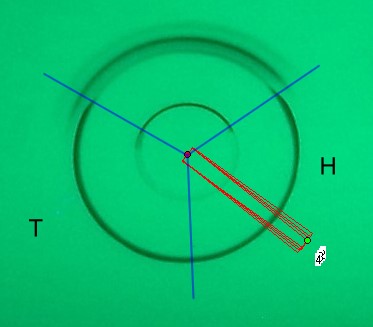
The following compare chromatogram checks the composition of the product “H” versus the product “T”. The two samples have been brush sampled with a narrow overlapped region at the lower part of the chromatogram figure. For polarity control a color test mix is sampled at the upper part of the chromatogram. Product “H” looks like equal the product “T” - may be the only slightly visible “impurity” at a lower value for Pi . As mentioned above, Pi is the radius of the substances in the circular chromatogram of the compared substance bows.
. Now we wanted to know about how “clean” is substance “H” roughly expressed as integral of the bow area in %. We also wanted to know how accurate are such preliminary data. We reach for the “H” main compound a relative standard deviation of +- 0.05 %. NOTE: this is the comparability standard deviation of compared integrations. The four tracks have been turned by 1 degree. These are four chromatograms. µ-PLC is multi chromatography, there is not just one spot or one small sample streak, thus µ-PLC offes comparability data. For repeatability values we cannot find a useful value as it is all digital from the photo data to the accuracy of the integration source code. All below +- 0.001 %.The quantitative values from the raw four integration tracks extrapolated to the total bow area values are given in an enlarged part of the SORBFIL Videodensitometer report
(Version 2.01) in the next figure below. The extrapolation is simply possible, as the report is given as Microsoft Excel file and contains all values : “Mi” and “Pr” as mentioned in all details above.

bk-2011-report-chr

Compare chromatogram of medical products “H” versus “T”

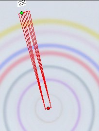
The red four overlapping and by always 1 degree angle turned integration tracks produce the raw data given in the report table below.The blue lines show sample overlap positions T over the test colors / test colors over H and H over T.

The test color mix contains a very polar substance - the sharp well visible bow at the smallest Pi value. The byproducts in “H” and “T” look like non sharp bows, either a mix of several by products or a substance which changes its chemical character during the run but still remains very strong polar. (In fact the analyst knows: it is an acid)

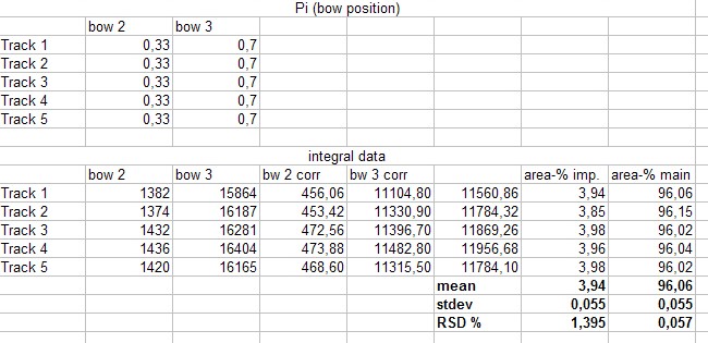
bk-2011-report

Above is the enlarged report
to the four integration tracks of the compare chromatogram “H” versus “T”. The Pr position of bow 2 (an impurity in “H”) is 0.33 based on 1.00 for the mobile phase front of the chromatogram. The raw integration values of the impurity is seen in the lines “bow 2” . Track 1 starts with 1382. The corresponding Pr value is 0.33 - see the Pr (bow position) value in Track 1 above.  Multiplying 1382 by 0.33 results in the corrected integral value for ”bw 2 corr” track 1 and shows 456.06. This way we correct all “bw 2” values and by the Pr value of 0.7 we correct all “bow 3” values. Now we add the corrected integral data  to its corresponding total in order to be able calculating the % integral-values for the impurity and for the main compound. The result under “area % imp” is 3.94%...a.s.o. and 96.06%... down to the “structure freed mean of 3.98 % impurity and 96.02 % main compound in the medical product “H”. The mean for all four measured tracks is 96.06 area-% for the main compound and 3.94% for the impurity. The main compound and the impurity have equal values for the comparability standard deviation: it is 0.055. NOTE: the fifth track is the graphical mean.

Standard deviation : +- 0.06 % for both !! .
This is of course preliminary and “relative”, not yet a final quantity value. BUT: Not so bad for a preliminary quantitation in PLC, and by now only possible by
µ-PLC in multi circular quantitation.

REMEMBER :
Integral values offer quantitatively much better comparable information by multiplication with the substance position in the circular chromatogram. Whether this is the bow- or circle radius or the relative position based on the mobile phase front at position 1.00 or if we use the circular position in percent of any selected upper border: it does not matter. Thus the first step to absolute quantitation  is very simple and the final processes are STANDARD as in all quantitative chromatography.


[Home] [Introduction] [Contents] [µ-PLC pictograms] [Multi Integration] [µ-PLC helps HPTLC] [Main errors in PLC] [Trace anal. by µ-PLC] [TLC HPTLC pictogr.] [Making a µ-PLC  instr.] [PLC literature] [sel. Summary] [Balaton Papers] [Basel-Paper-2011] [3-Phases-Chrom]